Menu


Troubleshooting Steps
| Step | Action | Reaction | Error | Remedies | |
|---|---|---|---|---|---|
| 1 | Connect to computer | ||||
| 2 | Push power button | White screen, green pulsing LED | No reaction | Push power button again. Check (+) and (-) to make sure they are not accidentally connected to each other. Replace cable to computer. | |
| 3 | Open Mu editor | ||||
| 4 | Open Serial dialogue in Mu | ||||
| 5 | Click in Serial, ctrl-c | Adafruit CircuitPython 5.3.0 on 2020-04-29; Adafruit Feather M4 Express with samd51j19 | |||
| 6 | Click in Serial, ctrl-d | code.py output: Hello World! | |||
| 7 | Double click reset button | Drive listing on host computer becomes FEATHERBOOT: | |||
| 8 | Copy file adafruit-circuitpython-feather_m4_express-en_US-7.2.5.uf2 to FEATHERBOOT drive | FEATHERBOOT drive self-ejects, becomes CIRCUITPY drive. | |||
| 9 | Reopen Serial on Mu. ctrl-c | Adafruit CircuitPython 7.2.5 on 2022-04-06; Adafruit Feather M4 Express with samd51j19 | |||
| 10 | Copy folder lib to CIRCUITPY drive. If asked, replace existing folder. | ||||
| 11 | Serial, ctrl-d | initialized indicator, no other reaction | Wiring fault in LED circuit | Check A56-GND, A55-(+), LED case flat on underside of board, 100Ω resistor (+) to A60, LED - lead to B55, LED + lead to B60. | |
| 11 | Serial, ctrl-d | initialized indicator, blinking LED | indicator OK | ||
| 11 | Copy test_codes, blink_indicator, code.py | No reaction | Serial in REPL mode. | ctrl-d to resume | |
| 12 | Copy test_codes, display_screen, code.py | initialized display, STELLA splash screen showing | >>>, no display showing | ctrl-d to resume | |
| 13 | Copy test_codes, pushbutton, code.py | Ready: push record/pause button to test it, pushing the button toggles between modes 0 and 1 | no change of mode showing. | Check pushbutton wiring, to (-) and to blue wire. Check capacitor installed with correct polarity. | |
| 14 | Copy test_codes, i2c_bus_scan, code.py | I2C addresses found: ['0x18', '0x49', '0x5a', '0x68', '0x77'] | Fewer than 5 addresses showing. | Check wiring for the sensor whose address is not showing in the list. | 0x18 -- AT Air Temperature - MCP9808
0x49 -- VIS 6 channel Spectrometer - AS7262 0x5a -- TIR Surface Temperature - Melexis MLX90614 0x68 -- clock: Real time clock - PCF8523 0x77 -- WX BME280 weather sensor |
| 15 | Copy test_codes, WX_pressure_temperature_humidity, code.py | If successful:
Temperature: 24.7 C Humidity: 50.2 % Pressure: 1011.9 hPa Altitude = 11.02 meters | If unsuccessful:
Traceback (most recent call last): File "code.py", line 14, in File "adafruit_bme280/basic.py", line 250, in humidity File "adafruit_bme280/basic.py", line 118, in _read_temperature File "adafruit_bme280/basic.py", line 150, in _get_status File "adafruit_bme280/basic.py", line 301, in _read_byte File "adafruit_bme280/basic.py", line 375, in _read_register OSError: [Errno 5] Input/output error | Check wiring of WX = BME280 sensor. | |
| 16 | Copy test_codes,, AT_air_temperature, code.py | If successful:
Temperature: 25.6875 C 78.2375 F | If unsuccessful: [test circuit does not induce error] | Check wiring of AT = MCP9808 sensor. | |
| 17 | Copy test_codes, VIS_spectrum, code.py | If successful:
Bright white source LED will shine briefly.
V:450nm: 15.9 B:500nm: 22.0 G:550nm: 25.1 Y:570nm: 23.9 O:600nm: 21.5 R:650nm: 18.7 | If unsuccessful:
Traceback (most recent call last): File "code.py", line 10, in File "adafruit_as726x.py", line 443, in __init__ File "adafruit_bus_device/i2c_device.py", line 61, in __init__ File "adafruit_bus_device/i2c_device.py", line 183, in __probe_for_device ValueError: No I2C device at address: 0x49 | Check wiring of VIS = AS7262 sensor. | |
| 18 | Copy test_codes, TIR_remote_temperature, code.py | If successful:
Object Temp: 24.29 | If unsuccessful:
Traceback (most recent call last): File "code.py", line 15, in File "adafruit_mlx90614.py", line 120, in object_temperature File "adafruit_mlx90614.py", line 123, in _read_temp File "adafruit_mlx90614.py", line 133, in _read_16 OSError: [Errno 5] Input/output error | Check wiring of TIR = MLX90614 sensor. | |
| 19 | Copy test_codes, NIR_spectrum, code.py | If successful:
Bright white source LED will shine at a couple of different brightnesses.
uW/cm^2 610nm: 12.8 680nm: 10.6 730nm: 19.5 760nm: 21.7 810nm: 18.0 860nm: 16.0 | If unsuccessful: [test circuit does not induce error] | Check wiring of NIR = AS7263 sensor. | |
| 20 | Copy test_codes, real_time_clock, code.py | If successful:
Clock battery voltage is OK. The date is Tuesday 2085-5-19 the day of the month is 19 the month is 5 The time is 22:36:09 | This reaction is the same whether or not there is a clock battery installed. If you haven't installed a clock battery already, please do so now. Then follow the instructions to set the clock to UTC. https://time.is/UTC | ||
| 21 | Copy test_codes, SD_card_write_read, code.py | If successful:
Printing lines in file: year month day batch checksum Program Completed | If unsuccessful:
Traceback (most recent call last): File "code.py", line 19, in File "adafruit_sdcard.py", line 100, in __init__ File "adafruit_sdcard.py", line 121, in _init_card OSError: no SD card | Two possible causes for this error: 1. No SD card installed. Install an SD card to correct this. 2. Adalogger has not been modified to connect the SD_CS chip select line to pin 11. If the SD_CS line is still connected to pin 10, the software won't find the card, even if there is one installed. Modify the Adalogger card as in the build instructions to correct this. | |
| 22 | Copy code-and-libraries, code.py to run the full STELLA code. | If successful:
Memory B: Used 136768 /Free 16640 begin infinite loop, mode == 0, and display will show data table. |
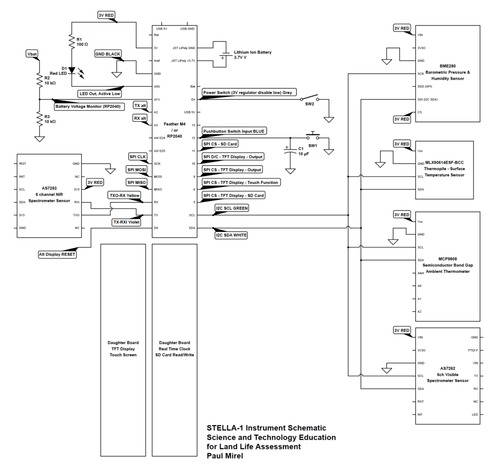
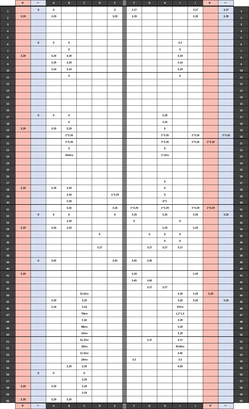
Wiring Voltages
Using your digital multimeter on the DC voltage setting you can check for proper voltages by holding the common ground (COM) black probe to a ground connection and the voltage red probe to check for voltages.

*Power on and screen removed
STELLA 1.0 Schematic