Source: The Landsat Tutorial Workbook

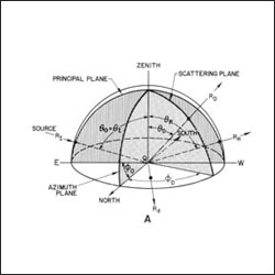
This schematic diagram depicts the behavior of a perfectly diffuse, or Lambertian, surface. This diagram appears in the The Landsat Tutorial Workbook: Basics of Satellite Remote Sensing written by Dr. Nicholas M. Short and published by the NASA Scientific and Technical Information Branch in 1982.
Dr. Short writes, “Consider a bundle of rays (making up the radiation flux) from a single distant source position at an incident angle θI (relative to the zenith direction) and an azimuth angle φ0 (relative to north). Imagine the (arbitrarily) horizontal plane of a target being irradiated to be enclosed in a hemisphere (this simplifies some calculations because it allows polar coordinates to be used [which we will ignore here]). For the wavelength conditions we set, the surface is considered rough or diffuse and has irregularities where the surface departs from horizontal, at varying slopes. A given ray RI located in the principal plane now strikes the surface at a point Q1. It will be reflected according to the position of the minute surface at Q depending on its slope. If that surface is horizontal (slope = 0°), the ray moves away along path RR in the principal plane as though this geometry is specular. But if the point surface QS is non-horizontal, i.e., has varying slopes defining the shape of the irregularity, the ray (mathematically treatable as a vector) will now move out along some direction RDthrough its scattering plane whose position is defined by θD and φD. At other points (Qn) on the surface, the direction of the outgoing R will differ according to the orientation of the slope at the immediate irregularity. Thus, a large number of incoming rays meeting the surface at other irregularities (most probably with randomly oriented slopes) will be redirected (diverge) in all possible directions extending through the hemisphere of reference.
The radiance in any one direction is, on average, the same as any other; in other words, radiance is constant at any viewing position on the hemisphere and is therefore independent of θ0. However, the radiant intensity at any position will vary according to the relation Iθ = I0cosθ. This states that as the angle of incident radiation Iθ is varied, the intensity of outgoing radiation also changes. For normal incidence (from the zenith), θ is 0 and cosθ is 1, so Iθ = I0. For all other angles cosθ is less than 1 and I0 is reduced. Although a homogeneous, non-variant surface viewed from any position will seem to be uniformly illuminated (constant radiance), that surface will become less bright as the source is moved from a vertical (overhead) position towards the plane itself (horizon).”
Space Oblique Mercator Projection
To continually map the Earth’s surface using Landsat data, an entirely new projection had to be created. This new projection was created by John Parr Snyder and is known as the Space Oblique Mercator (SOM) projection. This projection has been referred to as, “one of the most complex projections ever devised” by Library of Congress cartographic historian, John W. Hessler.

