
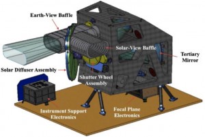
The OLI is a push broom sensor employing a focal plane with long arrays of photosensitive detectors (Irons & Dwyer, 2010). A four-mirror anastigmatic telescope focuses incident radiation onto the focal plane while providing a 15-degree field-of-view covering a 185 km across-track ground swath from the nominal LDCM observatory altitude (Fig 1).
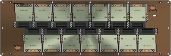
Periodic sampling of the across-track detectors as the observatory flies forward along a ground track forms the multispectral digital images. The detectors are divided into 14 modules arranged in an alternating pattern along the centerline of the focal plane (Fig. 2).
Data are acquired from nearly 7000 across-track detectors for each spectral band with the exception of the 15 m panchromatic band that requires over 13,000 detectors. The spectral differentiation is achieved by interference filters arranged in a “butcher-block” pattern over the detector arrays in each module. Silicon PIN (SiPIN) detectors collect the data for the visible and near-infrared spectral bands (Bands 1 to 4 and 8) while Mercury–Cadmium–Telluride (MgCdTe) detectors are used for the shortwave infrared bands (Bands 6, 7, and 9).
The OLI telescope will view the Earth through a baffle extending beyond the aperture stop. A shutter wheel assembly sits between the baffle and the aperture stop. A hole in the shutter wheel will allow light to enter the telescope during nominal observations and the wheel will rotate when commanded to a closed position and act as a shutter preventing light from entering the instrument. A second baffle, for solar views, intersects the Earth-view baffle at a 90° angle and a three-position diffuser wheel assembly dissects the angle. A hole in the diffuser wheel allows light to enter the telescope for nominal Earth observations.
Each of the other two wheel positions introduces one of two solar diffuser panels to block the optical path through the Earth-view baffle. When the wheel is in either of these two positions, the solar-view baffle will be pointed at the sun and a diffuser panel will reflect solar illumination into the telescope. One position will hold a “working” panel that will be exposed regularly to sunlight while the other position will hold a “pristine” panel that will be exposed infrequently and used to detect changes in the “working” panel spectral reflectance due to solar exposure.
Additionally, two stimulation lamp assemblies will be located just inside the telescope on the aperture stop. The two assemblies will each hold six small lamps inside an integrating hemisphere and will be capable of illuminating the full OLI focal plane through the telescope with the shutter closed. These assemblies, the shutter wheel, diffuser wheel, and stimulation lamp assemblies, constitute the OLI calibration subsystem.
Excerpted from Remote Sensing of Environment 122, James R. Irons, John L. Dwyer, and Julia A. Barsi , The next Landsat satellite: The Landsat Data Continuity Mission, 11-21, Copyright 2012, doi:10.1016/j.rse.2011.08.026, with permission from Elsevier
Courtesy of the journal Remote Sensing of the Environment

