


We originally designed the STELLA-1 instrument to work with the 2.4” TFT Touch Screen Display Featherwing, part number 3315, https://www.adafruit.com/product/3315
That display is out of stock, due to ongoing supply chain issues. While the Featherwing version is unavailable, we’ve developed a workaround to duplicate the functionality, so we can continue to make STELLA-1 instruments.
Tools Required
-
Wire cutter
-
Wire stripper -- 26-22 AWG
-
Needle nose pliers
-
Soldering iron, with a soldering iron stand
-
Lead-free solder, SAC305 alloy: Sn (tin) 97%, Ag (silver) 3%, Cu (copper) 0.5%
-
Desoldering braid
-
Safety glasses
-
Soldering fume exhauster
-
Full size breadboard, for use as an assembly fixture
-
Computer: A computer running either Apple Macintosh or Microsoft Windows operating systems
-
3D printer, fused filament type, 20 cm cube printing volume
-
Printer filament: black, white, blue
-
Ruler
-
Thin film double stick tape, for mounting the power buttonOptional
-
Solder sucker: suction desoldering toolOptional
Note: The 3D thermal sensor spacer and 3D Feather spacer should be printed before assembly.
Build Steps - Part 1 Wiring
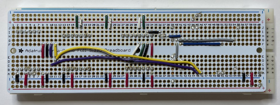
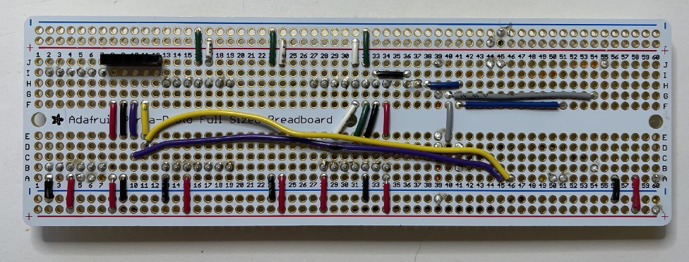
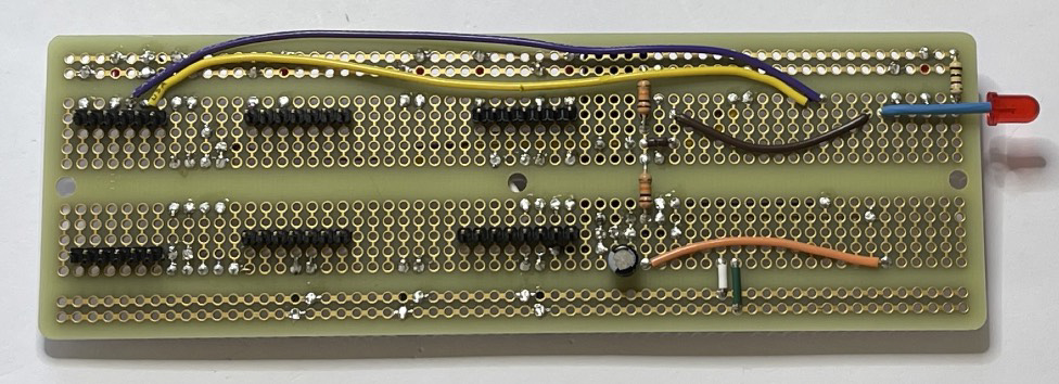
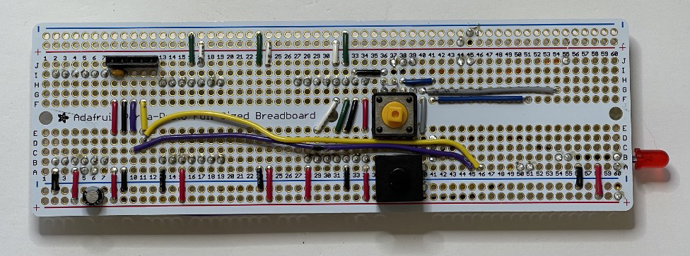
Following the STELLA-1.1 Wiring List, install and solder the resistors and then the wires. Lines 1 to 45 in the list. Leave some slack, as shown in the photos, on the yellow and violet wires, so that you can move them a bit when installing other components.
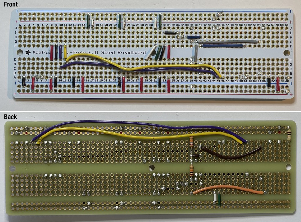
Double check your wiring against the wiring list to make sure that you have installed the wires correctly. It’s a lot easier to fix problems now, than to move wires around after other components are in place.
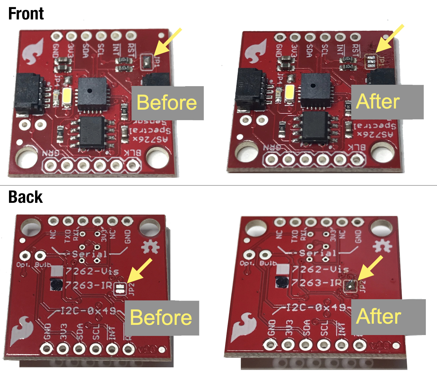
Build Steps - Part 2 Modify Near Infrared Sensor
Modify Near Infrared Sensor, line 46. Using desoldering braid, remove the solder from JP1 on the front of the board. Then add solder to JP2 on the back of the board.
Build Steps - Part 3 Install Headers
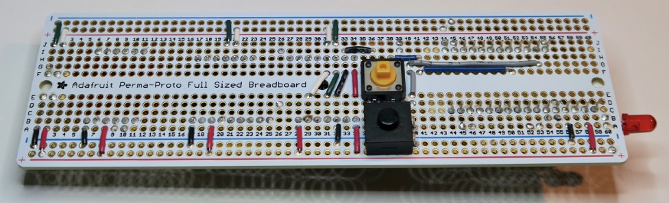
Lines 47 to 50. Break pin header segments to the required lengths, then fixture the segments in a breadboard.
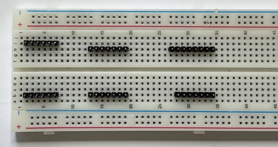
Place the STELLA main board on the fixture assembly, checking that the pins show in the correct locations on the board. Solder the pins in place, then carefully pry the board with the pins off of the breadboard fixture.
Build Steps - Part 4 Short Socket Header
Line 51. Trim a segment of short socket header to 5 positions. Secure on the front of the main board with a piece of tape, then solder on the back of the board.
Build Steps - Part 5 Discrete Components
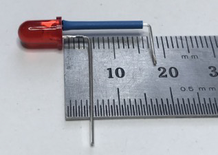
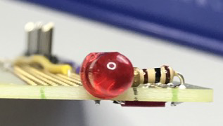
Lines 52 to 57. Install the remaining discrete components. Bend the LED leads, and install a piece of tubing, as in the photo. Note that the longer, positive lead is the one that we bend at 5mm, and the negative lead, near the LED case flat, we bend at 18mm.

Note also that the electrolytic capacitors (10 uF) have a white stripe to indicate the negative lead, and that the positive lead is the longer of the two. Install them in the correct polarity according to the wiring list.
Build Steps - Part 6 Modify the Datalogger
Line 58. Modify the datalogger by cutting the circuit trace labelled SDCS, and adding a wire to connect the SDCS to a new location (D11).
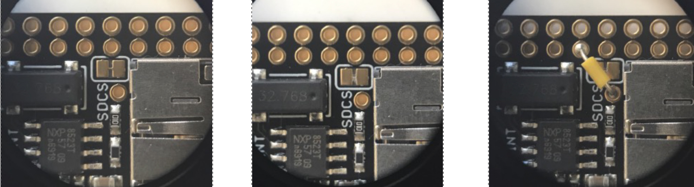
Datalogger before trace cut.
Datalogger after trace cut.
Datalogger with SDCS wire in place.
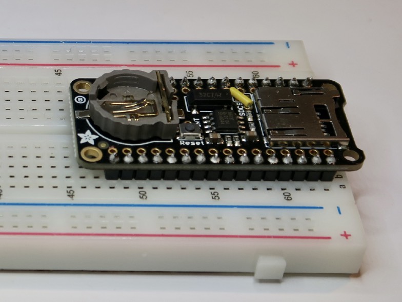
Using the breadboard as a fixture, install the header pins on the outer sets of holes on the datalogger.
Build Steps - Part 7 Microprocessor
Line 59. Using the datalogger as a fixture, place the stacking headers and install and solder the Feather RP2040 microprocessor.
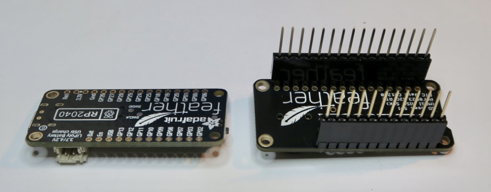
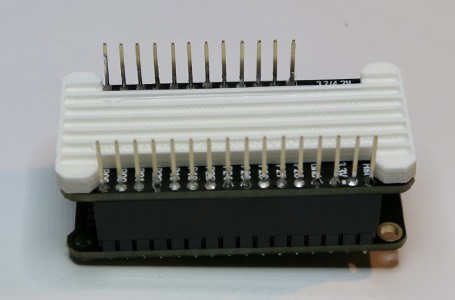
Then place the 3D printed part “feather spacer” on the back of the microprocessor.
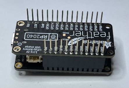
Lines 60 and 61. Mount the microprocessor to the main board assembly and solder the pins in place. Solder these joints carefully, to avoid getting solder on the tips of the pins, which we will use later to connect to the display.
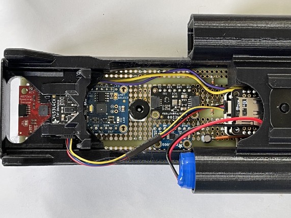
Build Steps - Part 8 Mount Sensors
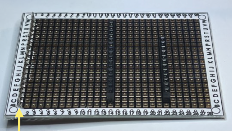
Lines 62 to 66. Mount the sensors. Install the Thermal Infrared (TIR) sensor on the 3D printed part “TIR sensor holder 4.5mm” before installing it on the main board.
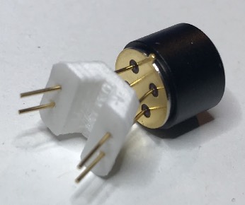
Note the position of the orientation tab, towards the VIS Spectral Sensor, as indicated by the angled yellow arrow.
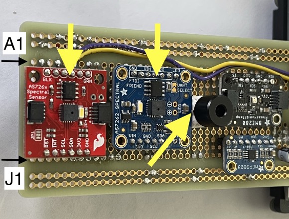
Also note the location of the communications chips on the spectral sensors. The sensors should be installed so that these chips are closest to the A row, as indicated by the yellow arrows.
Install the datalogger by stacking it on the microprocessor. Insert the clock battery and micro SD card.
Build Steps - Part 9 Display Board
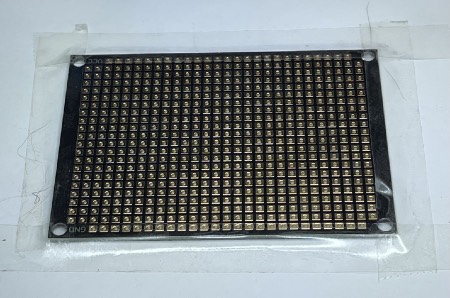
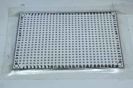
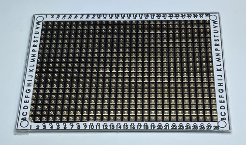
Prepare the display mount board: On an ordinary office paper printer, print the file “protoboard DFRobot FIT0203 print” at full scale. Apply clear double stick tape to the protoboard, then apply the printed column and row dataframe, and trim the excess and center out as shown.
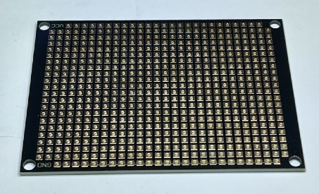
Orient the board so that the VCC label Apply clear double stick tape to the shows in the upper left, and the GND label outer frame of the board. is in the lower left.
Orient the board so that the VCC label Apply clear double stick tape to the shows in the upper left, and the GND label outer frame of the board. is in the lower left.
Carefully align the print to the edges of the board.
Trim the excess tape from the outer edge and remove the central part of the print.
Build Steps - Part 10 Display Board Headers
Lines 68 and 69. Place short header sockets, 12 pin and 16 pin, on the labeled side of the board. Secure them temporarily with tape and solder them on the other side of the board.
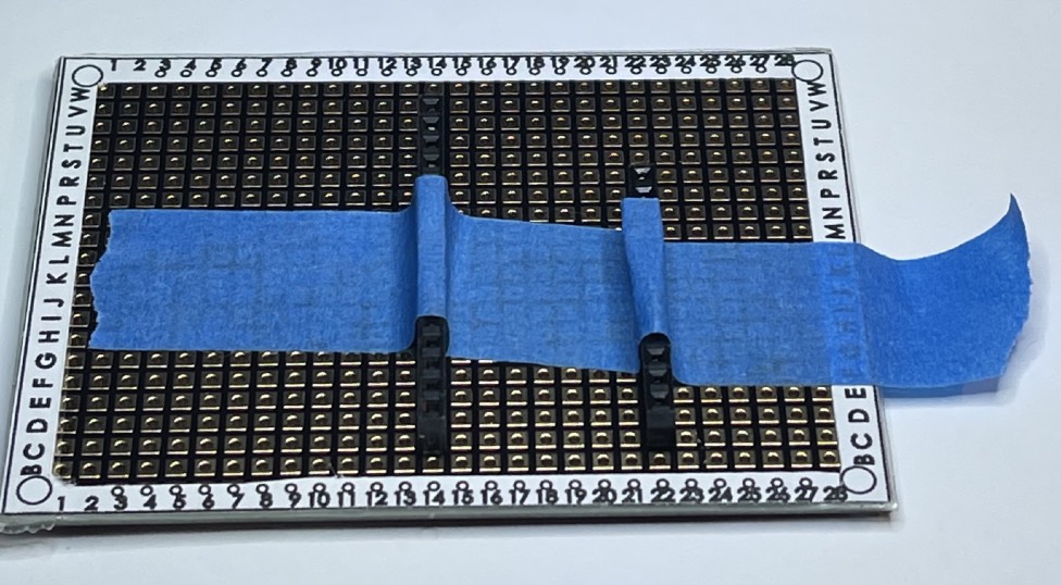
Line 70. Install a 20 position pin header from the back of the board (blue arrow), and solder it on the front (yellow arrow)
Build Steps - Part 11 Display Board Wiring
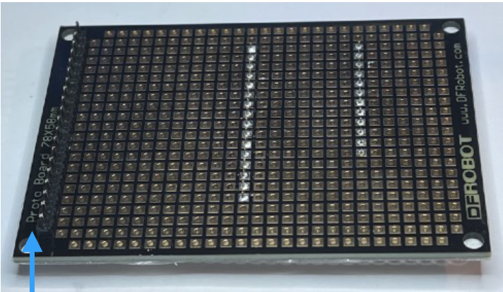
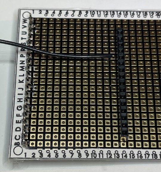
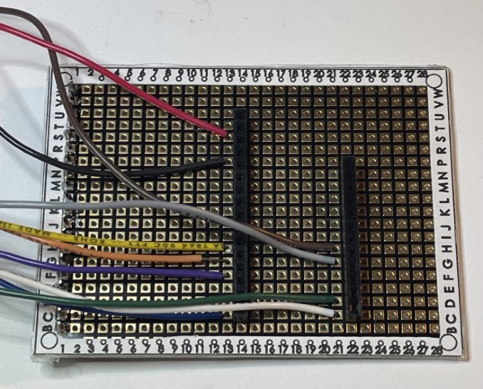
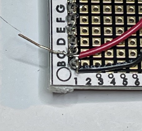
Lines 71 to 80. Connect wires to header socket positions. Since the board does not have traces that connect any hole to any other hole, we must make the connections ourselves. Here we show the black wire, poking through P13 from front to back, and then we see the back of the board where we bend the wire around the pin at P14. Make connections like this for each wire.
Build Steps - Part 12 Display Board Wiring and Headers
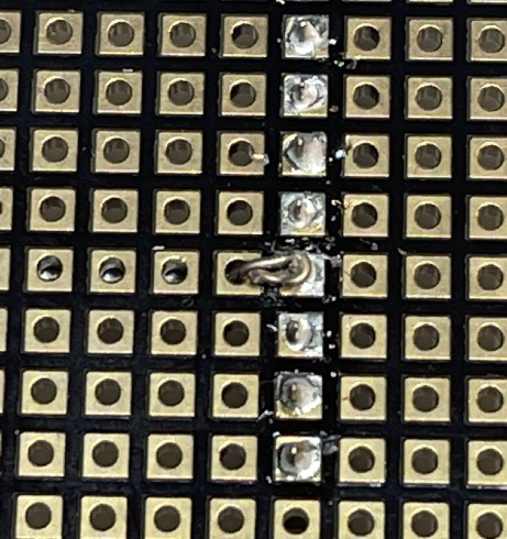
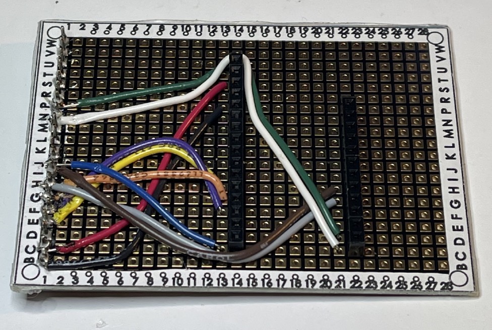
Lines 71 to 80. Connect wires to the header pin positions. Here we show the black wire already soldered and trimmed, and the red wire placed, wrapped around the pin, ready for soldering. Make these connections for each wire to the positions listed in the wiring list.
Build Steps - Part 13 Display Board Wiring and Headers
Line 81. Solder the IM1, IM2, IM3 jumpers closed on the back of the display. Do not close IM0.
Place the display spacer, 3D printed part “STELLA-1.1 screen spacer in print coords”, on the back of the display.
Apply clear double stick tape to the face of the spacer. Then align the wiring board pins with the holes on the display, to make a sandwich: Wiring board, tape, spacer, display. Trim off the excess tape, and solder the pins to the display board. Trim the excess length of the pins using a diagonal cutter.
Build Steps - Part 14 Mount Display
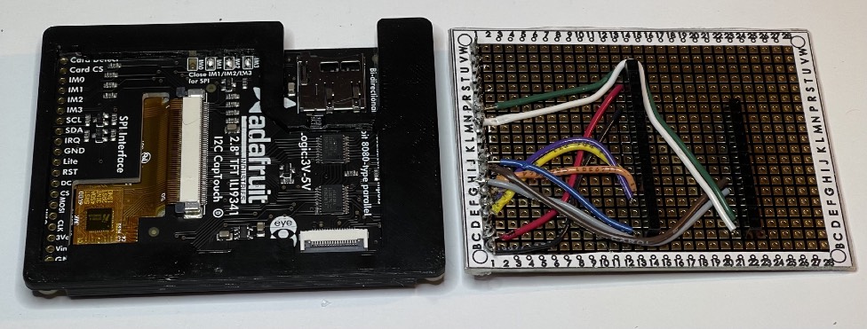
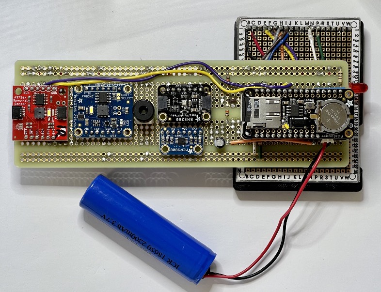
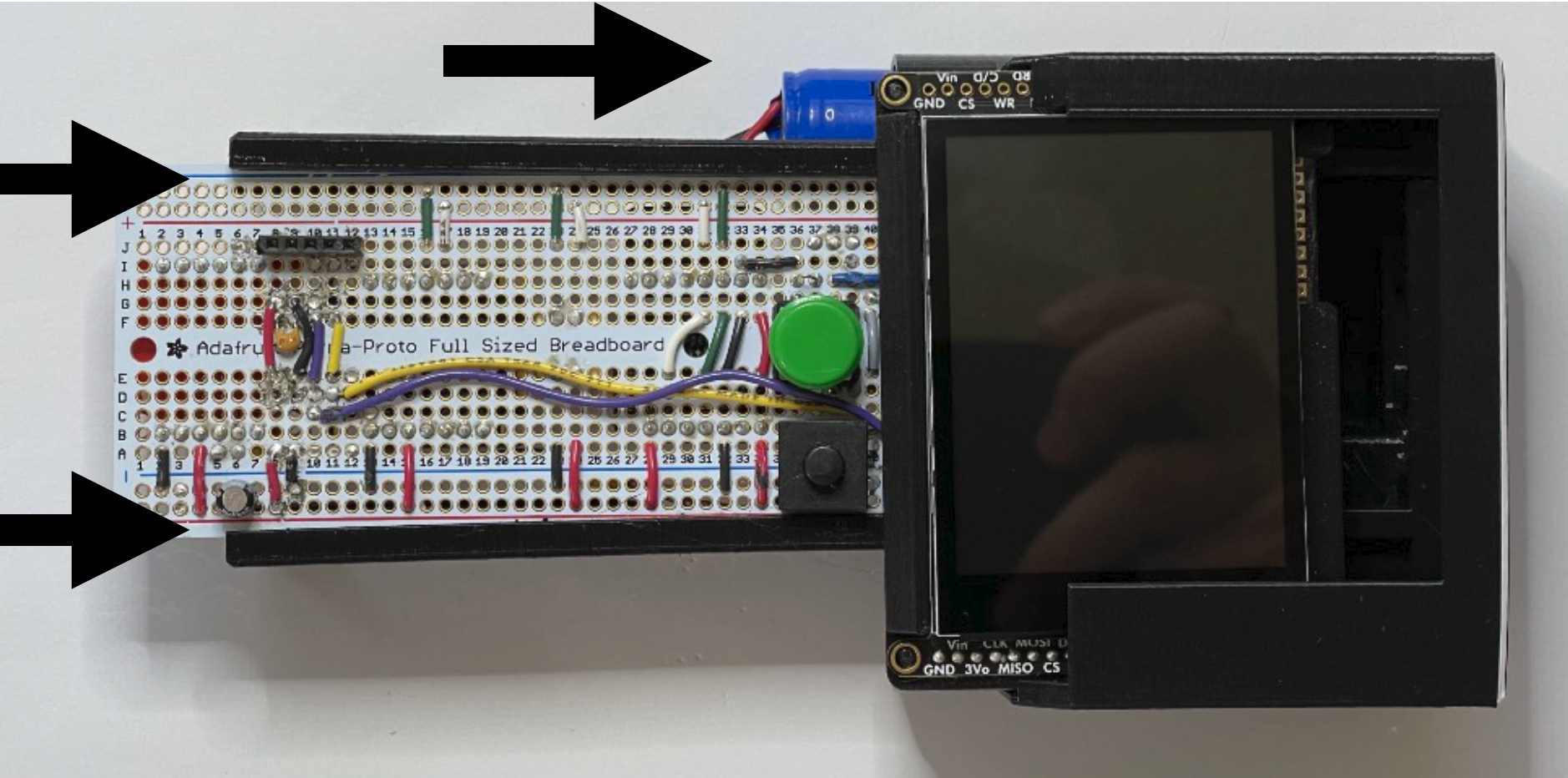
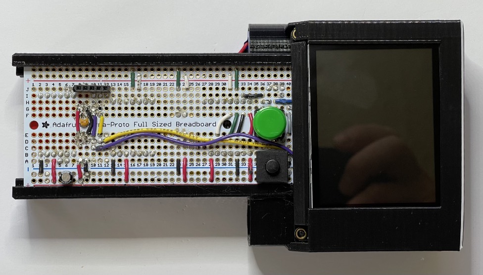
Mount display: align the processor pins on the main board with the socket headers on the display board, on both the 12 and 16 position connections. Press gently to seat the display. Connect the main battery to the power connector.

Build Steps - Part 15 STELLA Assembly
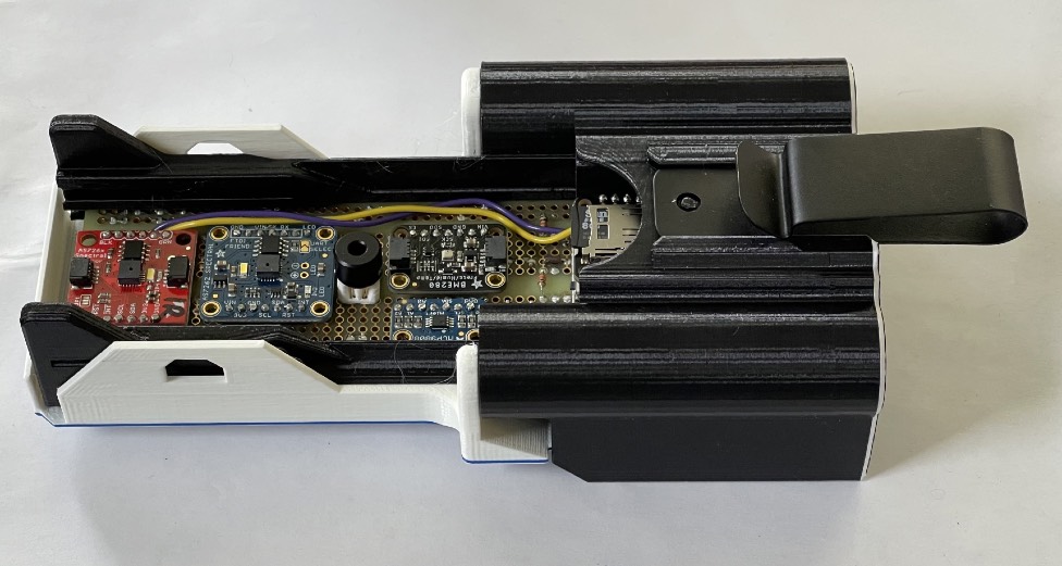
Slide the STELLA assembly into the long grooves of the lower housing, while sliding the main battery into the cylindrical battery holder tube. You may need to press gently on the display to get it to slide into the housing recess. “STELLA-1.1 Lower Housing”
Build Steps - Part 16 STELLA Upper Housing
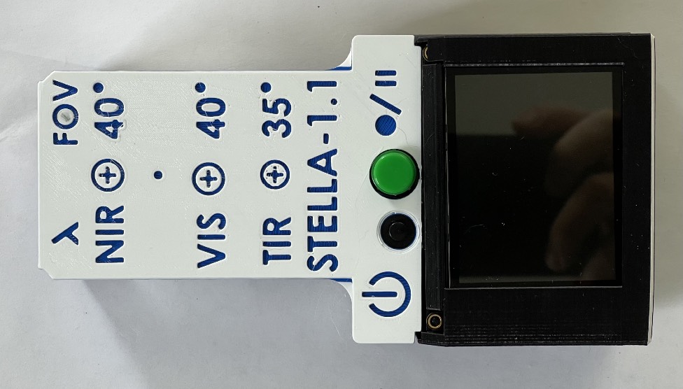
Install Upper Housing: Align the upper housing with the buttons, and press it onto the lower housing so that it snaps into place.”STELLA-1.1 Uppper Housing 3 band”
Slide the optional belt clip into place in the grooves on the bottom of the housing. Push gently with a finger nail or pen tip on the retainer pin to release and remove the clip.
*Build Steps - Part 17 STELLA LIDAR
Slide the optional LiDAR range measurement sensor into the 3D printed part “STELLA-1.1 LiDAR mount print coordinates”, and then connect the qwiic cable to the sensor.
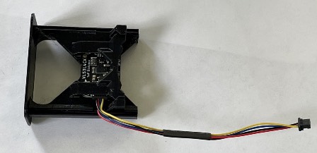
Slide the mount into the dovetail grooves in the lower housing, and then connect the cable to the qwiic port on the end of the microprocessor.
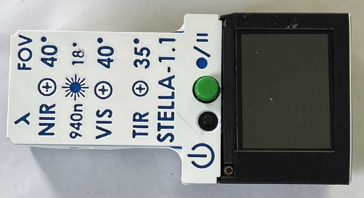
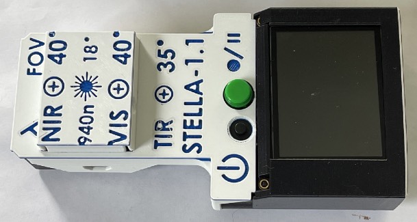
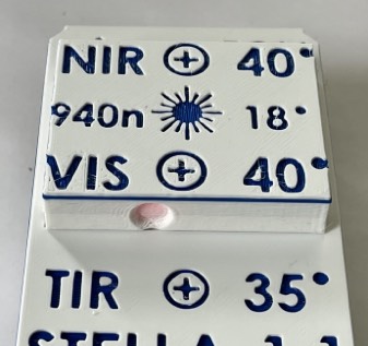
Switch out the upper housing for the version with the LiDAR markings, which show the wavelength and field of view of the sensor. “STELLA-1.1 Upper Housing LiDAR mark”
*Build Steps - Part 18 STELLA GPS
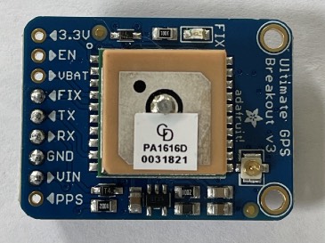
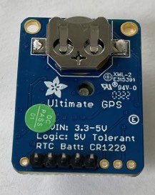
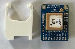
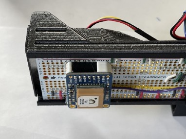
Position the GPS spacer (“STELLA-1.1 gps spacer in print coordinates”) under the GPS sensor, and connect the sensor at the 5 pin short socket header on the top of the STELLA board.
Change to the GPS housing to accommodate the extra height on the board. The GPS status indicator light is visible in the round window. “STELLA-1.1 Upper Housing gps hat with window” and “ STELLA-1.1 Upper Housing GPS outer”
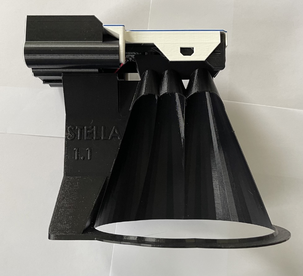
*Build Steps - Part 19 Beam Definition
Install the beam definition model in the dovetail grooves in the lower housing. (You’ll need to remove the LiDAR sensor, if you have it installed.) “STELLA-1.1 beam def in print coords.STL” The model shows the field of view of the spectral sensors and the thermal infrared surface thermometer sensor. You can do the trigonometry to figure out the diameter of the observed area based on how far away the unit is from the surface, given the 40º field of view of the sensors.
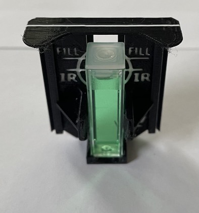
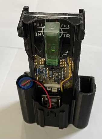
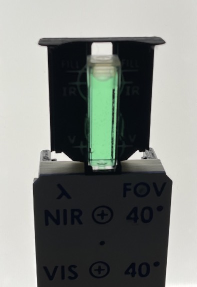
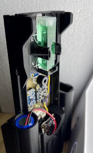
*Build Steps - Part 20 Cuvette Mount
Print the part “STELLA-1.1 cuvette mount in print coords” to hold cuvettes in the field of view of the NIR and VIS sensors. Cuvettes are square test tubes used for testing the optical properties of liquids.
Fill a cuvette with distilled water, and fill another with the liquid you wish to test. Slide the cuvette holder into the dovetail grooves on the lower housing, and snap the cuvette in place to take a measurement. Take two measurements, one of each of the liquids you wish to compare, and subtract the results to get a differential measurement of the transmission spectra of the liquids.
* Any use of trade, firm, or product names is for descriptive purposes only and does not imply endorsement by the U.S. Government.
