Tools Required
-
Wire cutter
-
Wire stripper -- 26-22 AWG
-
Needle nose pliers
-
Soldering iron, with a soldering iron stand
-
Lead-free solder, SAC305 alloy: Sn (tin) 97%, Ag (silver) 3%, Cu (copper) 0.5%
-
Desoldering braid
-
Safety glasses
-
Soldering fume exhauster
-
Full size breadboard, for use as an assembly fixture
-
Computer: A computer running either Apple Macintosh or Microsoft Windows operating systems
-
3D printer, fused filament type, 20 cm cube printing volume
-
Printer filament: black, white, blue
-
Ruler
-
Thin film double stick tape, for mounting the power buttonOptional
-
Solder sucker: suction desoldering toolOptional
Note: The 3D thermal sensor spacer and 3D Feather spacer should be printed before assembly.
Build Steps - Part 1 Wiring

Step 1: Ground (black wire):
Front: Connect each to (-) bus below A row.
☐ A1
☐ A7
☐ A18
☐ A34
☐ A56
Front: Connect point to point.
☐ E34 - E39
☐ H39 - H40

Step 2: Brown Wires:
Front: Connect point to point.
☐ J38 - J43
☐ G43 -G46

Step 3: Red Wires:
Front: Connect each to (+) bus below A row.
☐ A2
☐ A9
☐ A20
☐ A35
☐ A37
☐ A58

Step 4: Yellow wire:
Back: Connect point to point.
☐ A11 - A46

Step 5: Green wires:
Front: Connect each to (-) bus above the J row.
☐ J1
☐ J21
☐ J33
☐ J45
Front: Connect point to point.
☐ F33 - E33

Step 6: Blue wire:
Front: Connect point to point.
☐ H41 - H51
Back: Connect point to point.
☐ E36 - C41

Step 7: Violet wire:
Back: Connect point to point.
☐A10 - A45

Step 8: Grey wire:
Front: Connect point to point.
☐ E43- H54

Step 9: White wires:
Front: Connect each to (+) bus above the J row.
☐ A2
☐ A22
☐ A32
☐ A44
Front: Connect point to point.
☐ F32 - E32
Build Steps - Part 2 Header Pins
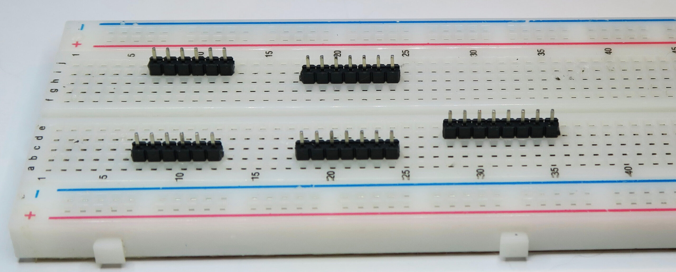
Step 1: Push headers into breadboard
Push the shorter end of the pins into the breadboard. It's a bit tricky to get them to stay.
☐ 7-12 B (6 pins)
☐ 7-12 I (6 pins)
☐ 18-24 B (7 pins)
☐ 18-24 H (7 pins)
☐ 28-35 B (7 pins)
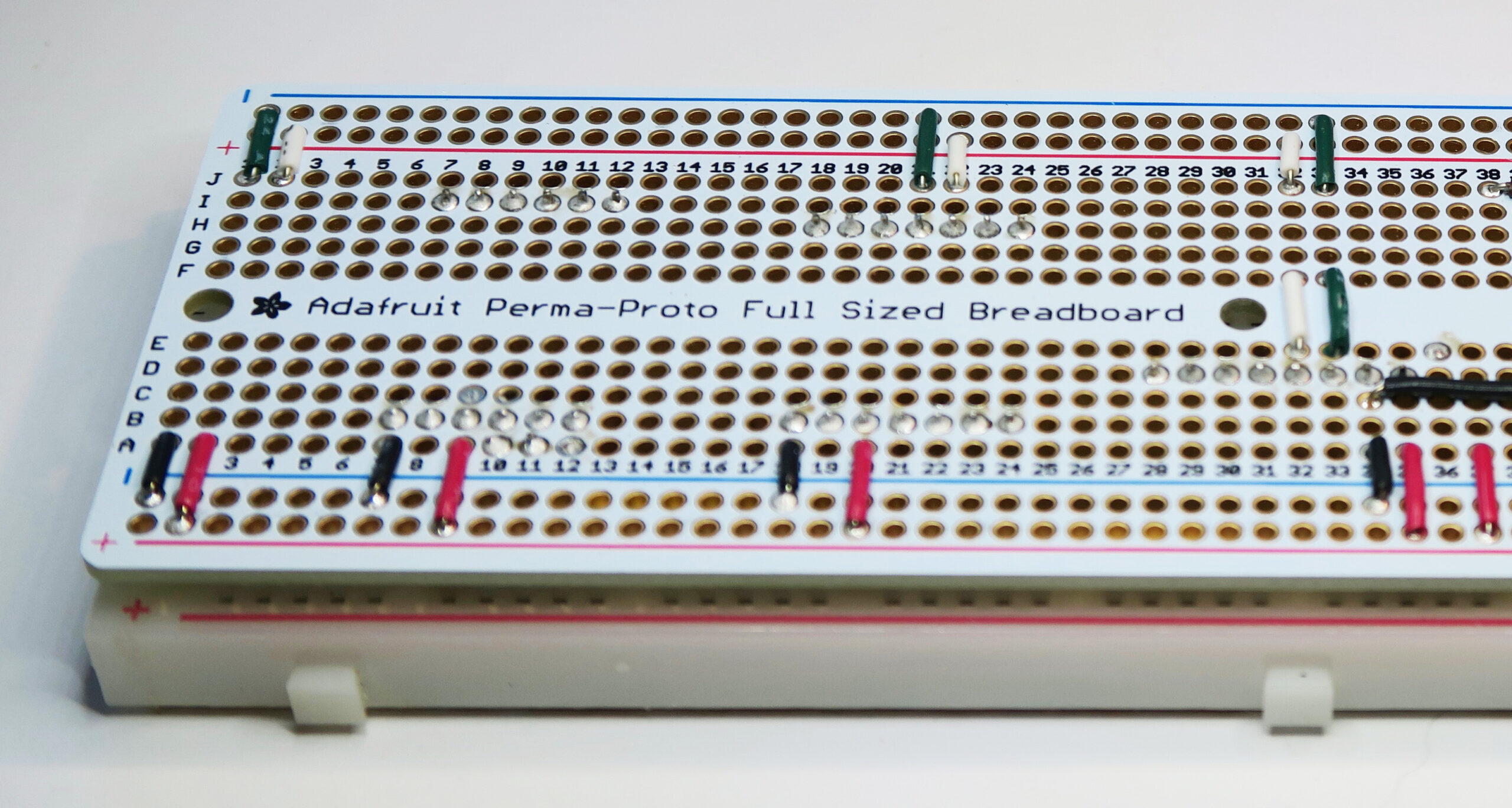
Step 2: Solder the pins to the protoboard.
Place the protoboard over the breadboard so that the pins poke through the protoboard at the correct locations. Solder the pins to the protoboard.
Build Steps - Part 3 Install Sensors
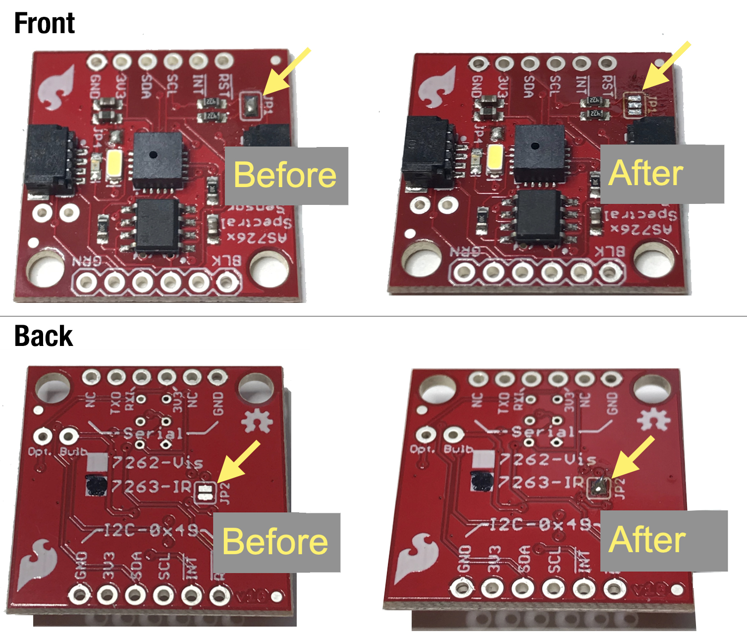
Step 1: Modify the NIR Sensor
☐ Remove solder from jumper set JP1 (on the component side of the board)
☐ Add solder to the jumper J2 (on the back of the board)

Step 2: Install the Air, Weather, Visible and NIR Sensors
Reminder: Make sure you modified the NIR sensor as in Part 4 Step 4. It's important to make this modification before mounting the sensor, as there is no access to the underside of the sensor (JP2) once it's installed.
☐ Install the Air Temperature sensor face up, on the back of the main board, on the header with 8 pins. Orient the sensor so that it sticks out towards the SCK and SDA connections. To get it to sit flat, solder one pin only, at first. Then remelt that solder connection and lift the sensor board by hand to make it flat. Remove the soldering iron and let the connection cool. Then solder the rest of the connections. Solder 8 places total.
☐ Install the Visible spectrum sensor next to the two previously installed sensors. Make certain that the auxiliary communications chip is on the same side as the WX sensor. Solder 14 places.
☐ Install the Near Infrared spectrum sensor, next to the VIS sensor. Make certain the auxiliary communications chip is on the same side as the corresponding chip on the VIS sensor. Solder 12 places.
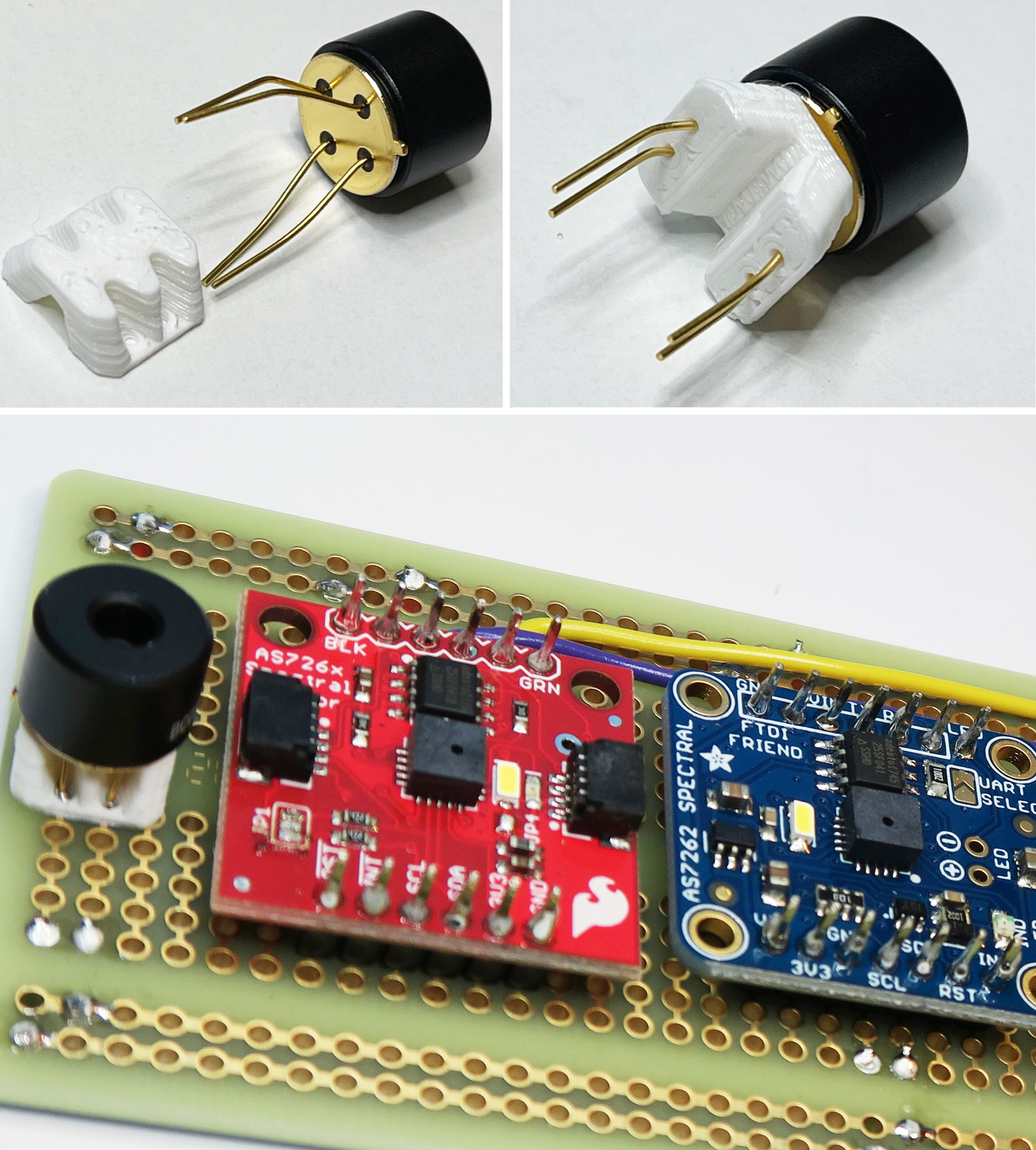
Step 3: Install the Thermal Infrared spectrum sensor
☐ Install the Thermal InfraRed non-contact surface temperature sensor at the end of the board.
☐ Bend the leads to fit into the spacer.
☐ Insert the leads into the holes in the spacer. Push the sensor flat to the spacer, then re-bend the leads to match the holes in the board.
☐ The sensor tab must protrude off one of the flat sides of the spacer. The sensor tab must point off the end of the board.
☐ Solder the leads in pins F1, F2, E1, E2, on the front of the board, then trim off the excess.
Build Steps - Part 4 Discretes
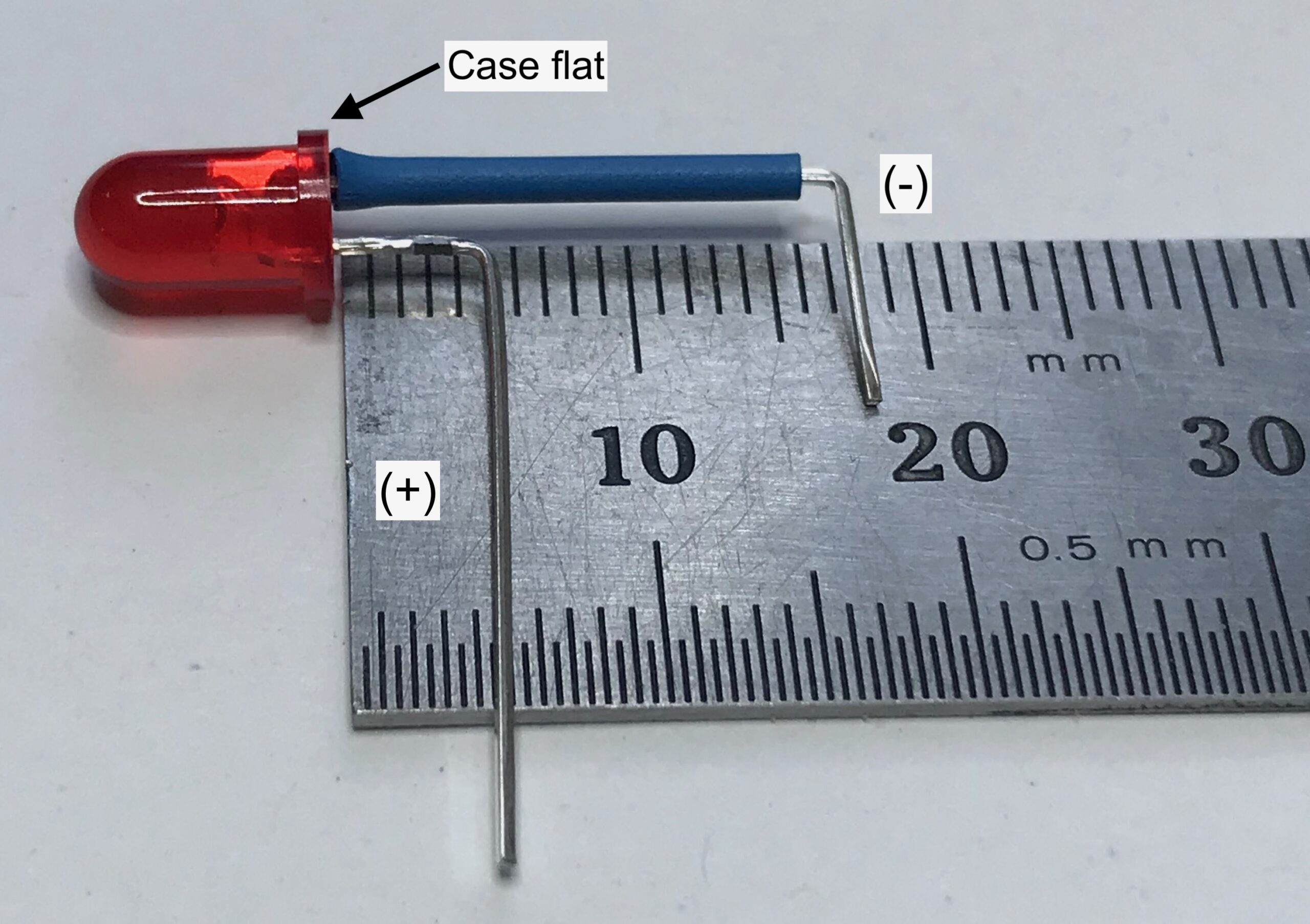
Step 1: Bend the LED leads
☐ Identify the negative lead: locate the flat on the case. That's the negative side.
☐ Bend the positive lead at 5mm (1/4") from the case
☐ Slip a piece of heat shrink tubing, 15 mm long, on the negative lead.
☐ Bend the positive lead at 18mm (3/4") from the case
Back: Connect two places
☐ positive lead to B60
☐ negative lead to B55

Step 2: Front LED, Resistor and Buttons
☐ Identify LED negative lead: locate the flat on the case. That's the negative side.
Front: Connect two places
☐ positive lead to I37
☐ negative lead to I38
Resistor: Connect two places
☐ E37
☐ F37
Power button: Connect two places
☐ A43
☐ (-) bus
Push button: Connect four places
☐ D39
☐ D41
☐ G39
☐ G41

Step 3: Back Capacitor and Resistor
Capacitor: Connect two places
☐ I40 (-)
☐ I41 (+)
Resistor: Connect two places
☐ A60
☐ (+) bus
Build Steps - Part 5 Assemble Datalogger
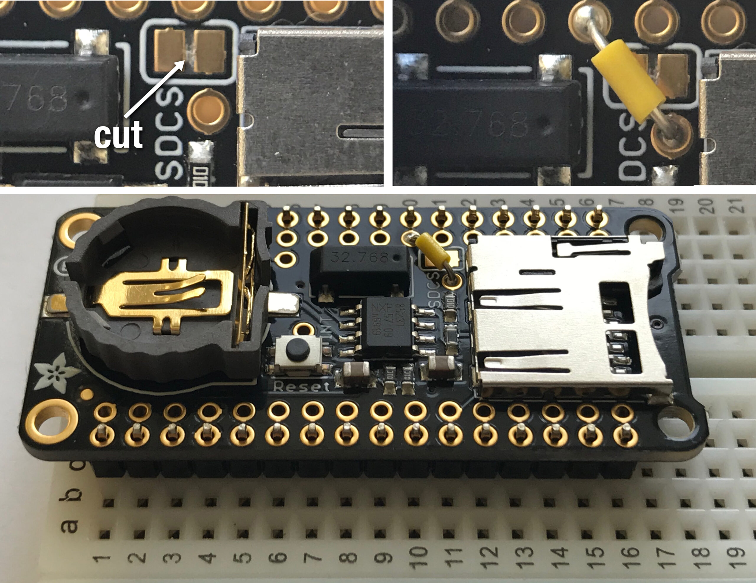
Step 1: Modify and assemble the datalogger board.
☐ Using a hobby knife, cut the circuit trace , marked SDCS, on the front of the board.
☐ Run a new SDCS line to the pin number 11 (yellow wire). Solder.
☐ Push the headers into breadboard, inserting the longer end of the pins into the breadboard. You may want to use something flat to push with to keep the pins from sliding in their plastic holders to different heights.
☐ Place the data logger board on the headers, on top of the breadboard. The pins should protrude through the outer sets of holes.
☐ Solder the header pins to the data logger card, 12 places and 16 places.
☐ Separate the datalogger board from the breadboard.
*SDCS = Secure Digital card Chip Select line, part of SPI (Serial Peripheral Interface) communications
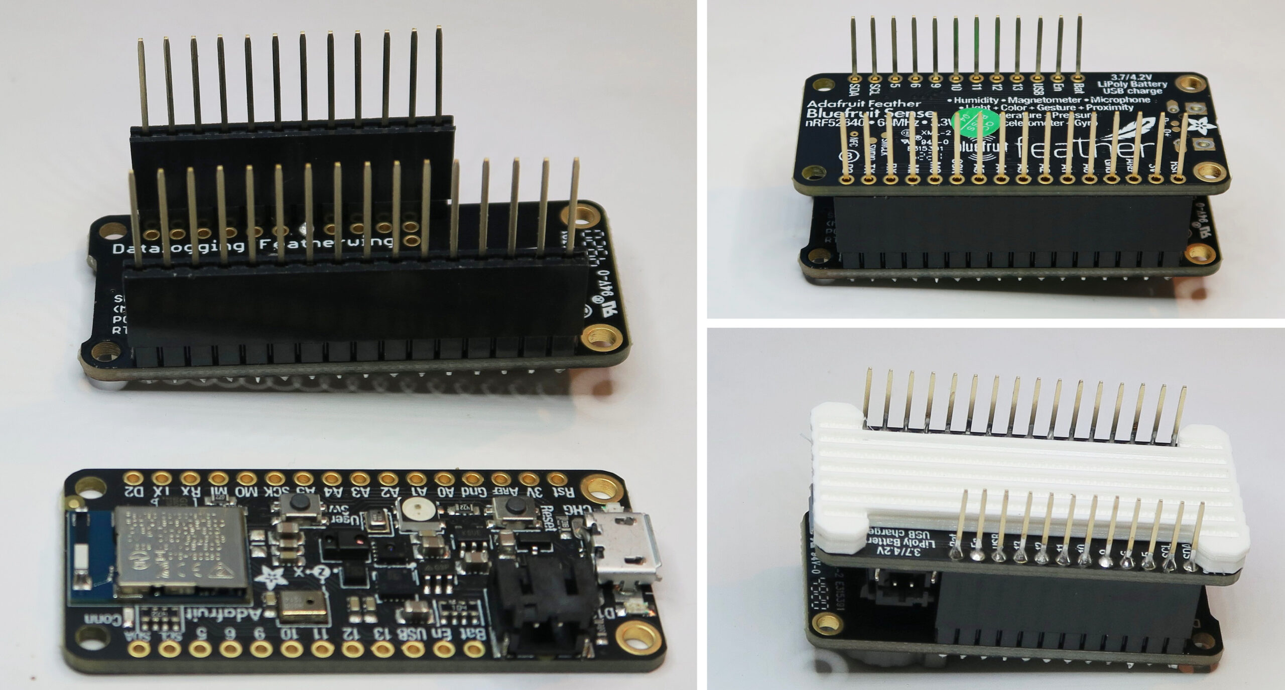
Step 2: Processor
☐ Push a set of stacking headers onto the datalogger card, to use the datalogger as a fixture to keep the headers at right angles to the processor board.
☐ Mount the processor on the headers.
☐ Solder each pin of the headers.
☐ Place the processor spacer on the processor.
☐ Mount the processor to the protoboard, from the back, into C44-59, and I44-55.
☐ Carefully solder the header pins to the protoboard. Once soldered, trim off the remaining length of the pins.

(Optional) Step 3: Connector
Install the connector for the wired remote pushbutton. The pin pitch of the connector is narrower than the hole pitch of the protoboard, so it takes careful alignment and a bit of force to seat the connector. Solder the three pins with the slot of the connector housing towards the center of the protoboard.
☐ B34
☐ B35
☐ B36
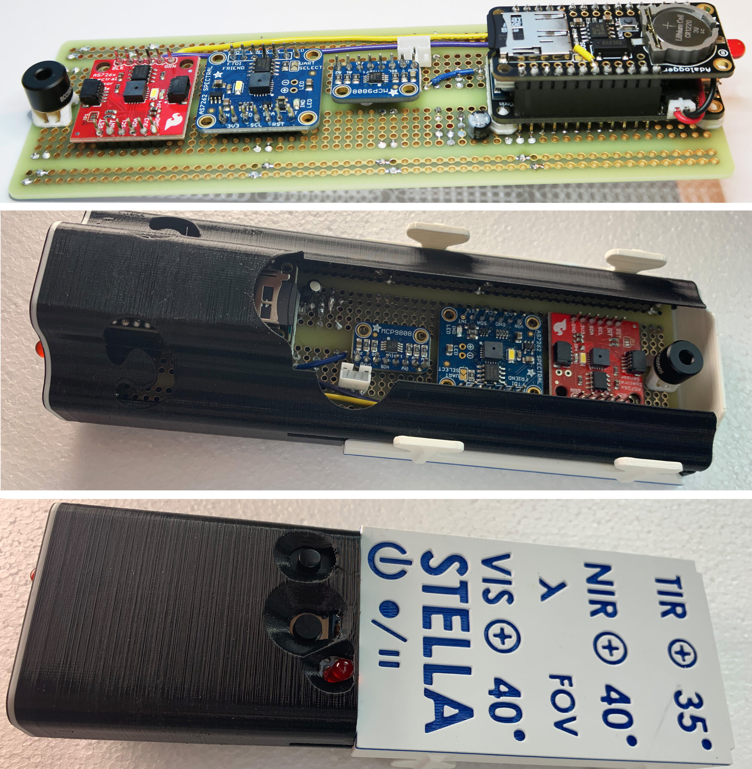
Step 4: Finish Up
Finish up: Remove the Adalogger, connect the main battery, then nestle the battery in between the headers on top of the microcontroller. The carefully reinstall the Adalogger over the microcontroller and battery. Install the coin cell battery, and insert the micro SD card.
Housing: Slide the completed STELLA-2 into the lower housing, then slide the upper housing on along the rails of the lower housing.
* Any use of trade, firm, or product names is for descriptive purposes only and does not imply endorsement by the U.S. Government.


