Build Instructions
To build a STELLA-Q you do not need any special tools; We build a working STELLA-Q with plug-in cables that connect components.
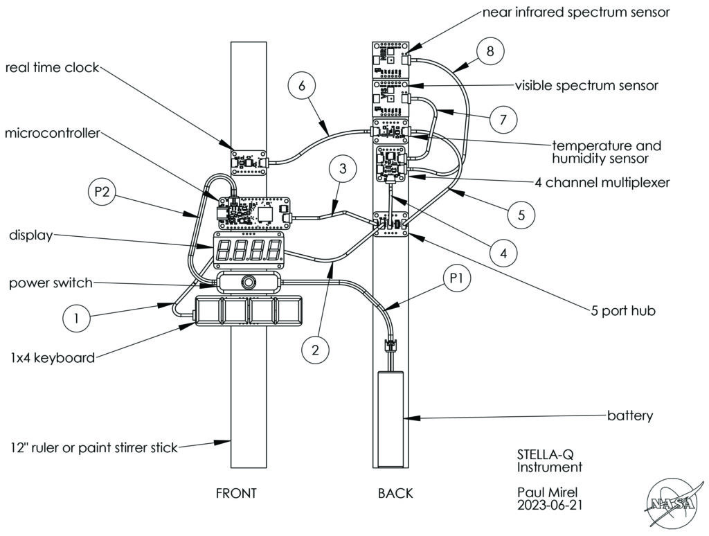
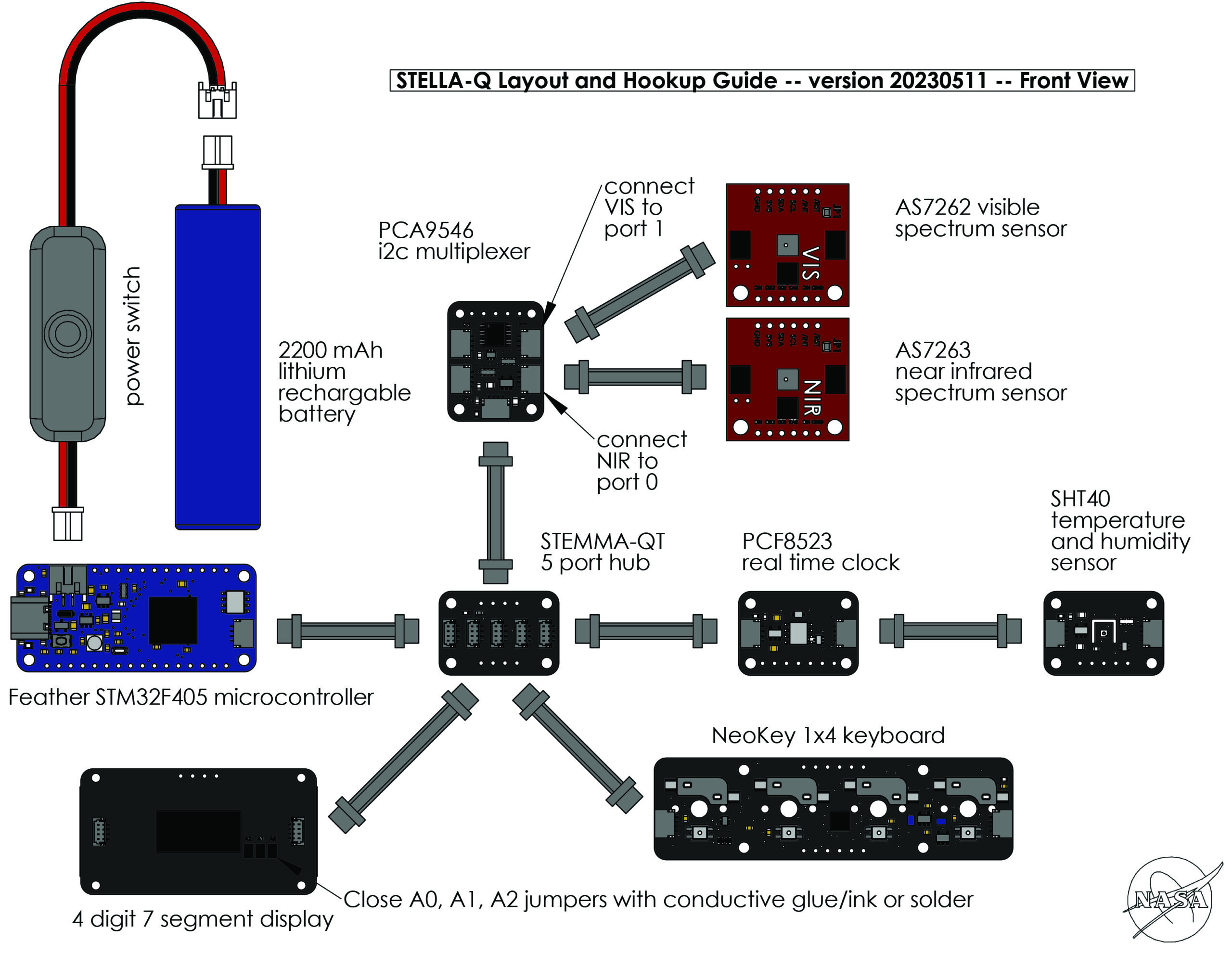
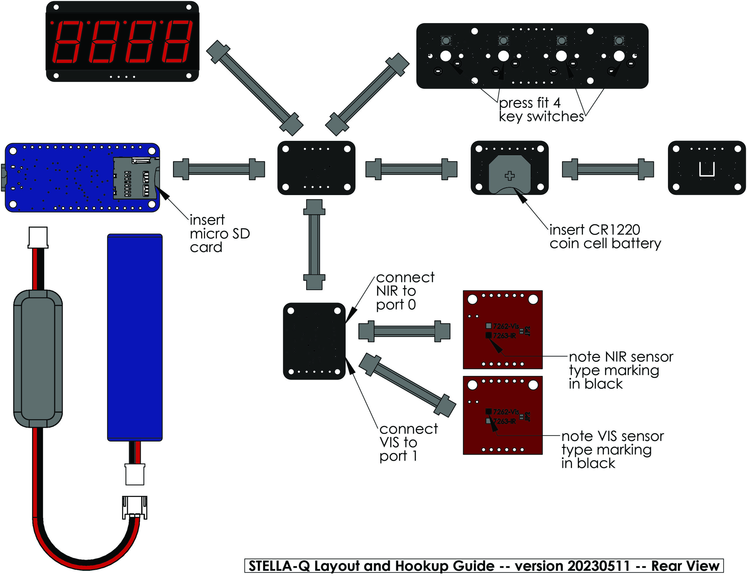
Print out the assembly sheet (front) and the rear side reference sheet. On these diagrams, the components are printed 1:1 scale.
Begin assembly by placing the components on top of their images on the sheet. The two spectral sensors are very nearly identical in appearance, but one senses visible light, and the other senses near infrared light. They are marked on the back, with a black ink spot on the label. We want to plug the NIR sensor into port 0 on the i2c multiplexer, and plug the VIS sensor into port 1 on the multiplexer.
The connectors are polarized: the cable connectors can only be plugged into the board connectors in one orientation. The connectors are small, and thus not very strong, so we need to push them together with care.
On one face of the cable connector, you will be able to see the underlying metal sockets, while on the other face you will see only plastic. The socket side of the connector faces the component circuit board when mating to the board connector, while the plastic side faces away from the circuit board. You may need to use your fingernails to press the edges of the cable connector toward the circuit board, to get it to connect fully.
Use the conductive ink pen and connect the jumpers (A0, A1, A2) on the back of the 4 digit display.
Connect all the components as shown on the layout sheet. The connections on the 5 port hub are identical, it doesn’t matter which components connect to which port. We wrote the software so that it will work even if one or more of the components are missing, so if you haven’t received a particular part yet, you can proceed anyway.
Connect the cable from the power switch to the battery connector on the Feather board. The connect the battery to the other end of the switch cable. The power switch disconnects the battery so we can turn the STELLA-Q off. The battery, when disconnected, will not charge. Turn the power switch on so that the STELLA is running off battery power, and then plug it in to USB-C, to charge the battery. There isn’t any way to charge the battery when the STELLA is off. That’s a design consequence of only using components that have preinstalled connectors on them.
Install the clock battery on the back of the Real Time Clock module. Insert the micro SD card into the slot on the back of the Feather microprocessor. Install the switches and switch caps on the 1×4 keyboard module.
We typically mount our components on a couple of craft sticks or a wooden ruler, using double-stick foam mounting tape. See the photo for an example arrangement. We want the display and keyboard facing up so we can interact with them, and we want the spectral sensors pointing down, and in the same direction, so they both see the same spot of light.
Connect the jumpers on the back of the You may want to add a drop of glue to hold the key switches in place on the 1×4 keyboard.